
The thermostat reads 61 degrees at 3:17 a.m. A January cold front has dropped overnight temperatures in Bonita Springs into the upper 30s. You raise the setpoint to 72. The indoor blower starts. The outdoor unit starts. Twenty minutes later the air leaving the supply registers is still room temperature. The system is running and it is producing no heat. This is how most heating failures present in Southwest Florida: the equipment operates, the thermostat is satisfied that a call for heat exists, and the house continues to lose temperature. You need heat restored before the next night, and you need a technician who can isolate a heat-pump reversing fault as readily as a failed heat-strip sequencer or a cracked igniter.
Dolphin Cooling & Heating, Inc. responds to this exact sequence every winter. We treat heating repair as a staged process that begins with the first description you give us and ends only after measured supply-air temperature, amperage, and safety-switch status confirm the system will hold through the remainder of the cold event. The steps below follow that sequence from the moment the heat stops until the system is verified and prepared for the next front.
Recording What Failed and Opening the Service Call
Before a technician arrives, the information you collect determines how quickly the fault can be isolated. Note the outdoor temperature, the thermostat setpoint, whether the outdoor unit is running, whether the indoor blower is running, and whether any air movement at the registers feels cooler, the same, or slightly warmer than room air. If the outdoor coil is iced, photograph it. If the indoor unit is making a new sound, record a short video. These details tell us whether we are looking at a reversing-valve problem, a defrost-control failure, an open heat-strip circuit, or a complete loss of ignition. When you call Dolphin Cooling & Heating, Inc. we use that information to decide which diagnostic instruments and replacement parts travel with the first truck.
Heating failures in Bonita Springs often occur after months of inactivity. A heat pump that has not reversed since April can seize a reversing valve, a heat-strip sequencer can corrode at the contacts, and a gas furnace inducer motor can lock from condensation that collected during the long cooling season. We ask whether the system has been used at all this winter and whether any recent electrical work or thermostat replacement occurred. That history lets us skip unnecessary tests and go directly to the circuits that sit unused for most of the year. Our 24/7 Emergency Service line is staffed for exactly these overnight temperature drops, so the same technician who would handle a mid-afternoon call is available when the house is already in the low 60s.
Site Arrival, Power Isolation, and Baseline Measurements
The first action on site is electrical isolation and a visual safety survey. We lock out the disconnect at the outdoor unit and at the indoor air handler or furnace, then verify zero voltage at the contactor, the heat-strip terminals, and the control board. Only after the system is confirmed de-energized do we remove access panels. We inspect the outdoor coil for ice or restricted airflow, the indoor coil for dust loading that would reduce heat transfer in heating mode, and the condensate pan and drain for standing water that can trip a float switch and lock out heat. We also check the thermostat wiring at both ends for loose or oxidized connections that appear only when the system switches from cooling to heating.
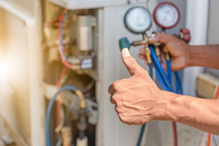
With power restored under controlled conditions we record baseline data. Outdoor ambient temperature, indoor dry-bulb temperature, supply-air temperature, return-air temperature, and the voltage at the indoor and outdoor units are written down before any component is swapped. On a heat pump we also record liquid-line and suction-line temperatures and pressures in the current operating mode. These numbers become the reference against which every subsequent test is compared. A heat pump that shows nearly identical liquid and suction temperatures has not reversed. A system whose heat strips draw far below nameplate amperage has an open element or a failed sequencer. We do not replace parts until the measurements identify the failed circuit.
Circuit-by-Circuit Fault Isolation
Heating systems in this climate use one of three primary heat sources: the heat-pump refrigeration cycle, electric resistance heat strips, or a gas-fired heat exchanger. Each source has its own failure modes and its own test sequence. We begin with the source the thermostat is actually calling. If the thermostat is configured for heat-pump operation we first confirm that 24-volt power is present at the reversing-valve solenoid when the system is in heating mode. We then compare line temperatures. A correctly reversed system will show a warm indoor coil and a cold outdoor coil. If the temperatures have not swapped, the valve itself or its solenoid is the fault. We test the solenoid coil for continuity and for the correct voltage under load. A valve that has mechanically seized is replaced as a complete assembly because internal leakage cannot be repaired in the field.
If the refrigeration cycle is reversing correctly but capacity is low, we recover, weigh, and compare the refrigerant charge against the factory specification for heating mode. Low charge reduces heating capacity more dramatically than cooling capacity because the outdoor coil is already working against a small temperature difference. We also force a defrost cycle and watch the board, the sensors, and the reversing valve to confirm the system can clear ice. A defrost board that never initiates, or a sensor that reads incorrectly, will leave the outdoor coil blocked and the indoor air barely warm. For electric heat we measure current draw on each heat-strip circuit and compare it to the nameplate rating. An open element, a failed sequencer, or a high-limit switch that has opened will show as missing amperage. For gas furnaces we verify inducer draft, pressure-switch closure, igniter glow or spark, flame-sensor microamps, and gas-valve operation in that order. We service and replace all brands, including Trane and Carrier equipment that uses proprietary control boards and communicating thermostats.
- Reversing valve and solenoid – Voltage at the coil, temperature split between liquid and suction lines, and mechanical shift of the valve are confirmed before any refrigerant work begins.
- Defrost control and sensors – The board is forced into defrost, sensor resistance is compared to the manufacturer temperature-resistance chart, and the outdoor coil is observed for ice clearance.
- Heat-strip circuits and sequencers – Each element is measured for current draw, sequencer contacts are checked for voltage drop, and high-limit switches are tested for continuity at operating temperature.
- Ignition and flame-proving components – Inducer vacuum, pressure-switch state, igniter current or spark, and flame-sensor microamp signal are recorded in sequence on every gas furnace.
- Control voltage and thermostat configuration – Twenty-four-volt power, common-wire integrity, and heat-pump versus conventional thermostat settings are verified so the equipment receives the correct call.
Performing the Repair and Restoring Measured Heat Output
Once the failed component is identified we replace it with a part that matches the original electrical and mechanical specification. A reversing valve is brazed in under nitrogen, the system is evacuated to the required micron level, and the exact factory charge is weighed back in. A heat-strip kit is installed with the correct kW rating and the sequencer is wired so the elements stage on without overloading the circuit. A gas valve or igniter is replaced and the manifold pressure is set to the rating plate. We do not leave a temporary jumper or a bypassed safety in place. Every safety switch that was opened during diagnosis is restored to its original circuit.
After the mechanical work we restore power and run the system through a full heating cycle. On a heat pump this includes a complete defrost if outdoor conditions require it. We watch supply-air temperature rise, confirm that the indoor blower remains on during the entire call, and verify that the outdoor unit does not short-cycle. On electric heat we confirm that all stages come on in the designed sequence and that the high-limit switch remains closed. On gas heat we confirm a stable flame, correct venting, and that the rollout and limit switches stay closed. If the original failure was caused by a related condition such as a restricted filter, a failing capacitor that starved the outdoor fan, or a thermostat that was set to emergency heat only, that condition is corrected at the same time so the new part is not immediately stressed.
Verification Testing and Documentation
A repair is not complete until the numbers match the design intent of the equipment. We record final supply-air temperature, temperature rise across the heat exchanger or indoor coil, outdoor-unit amperage, indoor-blower amperage, and, on heat pumps, the operating pressures in heating mode. These values are compared to the manufacturer’s allowable ranges for the outdoor ambient temperature at the time of the test. A heat pump that cannot produce the expected temperature split at 40 degrees outdoor air still has a charge or airflow problem. Electric heat that cannot reach the calculated temperature rise has an open element or insufficient airflow. We do not leave the site until those measurements are inside specification.
We also cycle the thermostat from heat to off to heat again to confirm the system restarts cleanly. We check that the outdoor disconnect and the indoor service switch operate correctly so the next person who services the equipment can isolate power safely. If the system is a communicating Trane or Carrier unit we review the control-board fault history and clear any codes that were generated during the failure. A written summary of the measurements, the parts replaced, and the remaining recommended work is left with you. When a repair approaches the practical limit of the equipment’s remaining life we provide a free estimate for replacement and we explain the financing options that are available so you can decide with the numbers in front of you rather than under pressure from a second night without heat.
Stabilizing the System for the Rest of the Cold Season
Heating equipment in Bonita Springs sits idle for most of the year. After a repair we address the conditions that allowed the failure to develop during that idle period. We replace a clogged filter, clean an outdoor coil that collected salt and dust, and confirm that the crankcase heater (if equipped) is operating so oil does not migrate and flood the compressor on the next start. We check the condensate drain and the auxiliary drain pan because a float switch that trips during a rare heating cycle will lock the system out just as effectively as a failed part. If the thermostat batteries are weak or the configuration does not match the equipment type, we correct that before we leave.
Dolphin Cooling & Heating, Inc. has performed residential heating repair, maintenance, and replacement since 1998. We focus on the homes of Marco Island, Naples, Bonita Springs, Ave Maria, Estero, Fort Myers, Golden Gate, Lely, Vineyards, North Naples, Orange Tree, and Pine Ridge, FL and we keep the same diagnostic sequence whether the call comes at 2 p.m. or 2 a.m. After the immediate repair we can schedule a follow-up inspection later in the season to confirm the system still meets the same temperature-rise and amperage values we recorded on the night of the failure. That second visit is the practical way to catch a related component that was stressed but not yet open. The goal is a heating system that starts, delivers the design temperature rise, and shuts down cleanly the next time a front moves through Bonita Springs, without another 3 a.m. call.